4. Boundary Conditions
While importing the Abaqus file, there are some boundary conditions that have already been specified. We wish to suppress these and instead define them natively inside Ansys Mechanical. Expand the Boundary Conditions Folder, right click on Constraints and pick suppress. This will deactivate all the boundary conditions that are included in the Abaqus model.
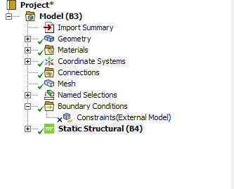
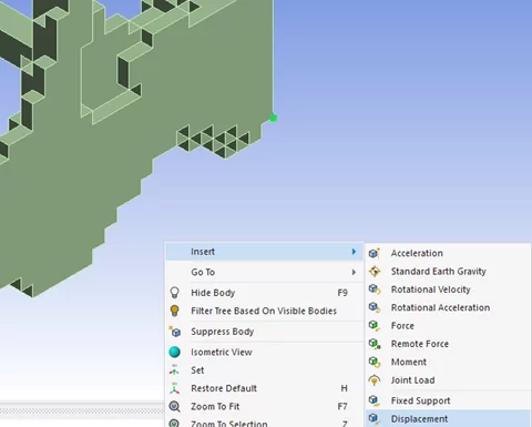
Right click on Static Structural (B4) and insert a displacement.

Change the Scoping Method to Named Selection and select top y. Enter -0.5 mm for the Y Component. This will assign a 0.5 mm displacement to the model in the -y direction on the faces selected for top y.
We can model the roller support as frictionless support in Mechanical. Right click on Static Structural (B4) and insert a frictionless support. Similarly, change the scoping method to Named Selection but select bottom y.

This will constraint the displacement in the y direction but the model will be allowed to displace in the x and z direction. This is very similar to the conditions of a roller support.
To prevent rigid body motion of the body, we need to constrain one vertex in x and z, and then another vertex in x to prevent rotation about y. Orient the model as shown. The easiest way is to click the sphere in the triad, and the model will align in the isometric orientation as shown.

Now zoom into the corner (+x,-y,+z) pick the corner vertex (highlighted in green), and right click and insert > displacement.

Set the displacement for x and z to 0 mm.

Zoom back out (F7) and zoom into the corner (+x,-y,-z) pick the vertex (highlighted in green) and right click and insert > displacement.
Set the displacement for x to 0mm. This will prevent rotation of the body about the Y axis.
The setup is finished. You may move on to setting up the solution.