Mesh — Lesson 4
Creating an Unstructured Mesh
Watch the following video for a demonstration on how to create an unstructured mesh for the airfoil using the "inflation" and "sphere of influence" features in the Ansys mesher. The advantage of this meshing strategy is that it can be adapted to complex geometries.
Skip to 'Named Selections' section below if you followed the video.
**ALTERNATIVE APPROACH**
NOTE: You can either create an unstructured mesh by following the above video or a structured mesh by following the steps below.
Create a Structured Mesh
Mapped Face Meshing
First, we will apply a mapped face meshing control to the geometry. In the Outline window, click on Mesh to bring up the Meshing Toolbar. In the Meshing Toolbar, select Mesh Control > Mapped Face Meshing. Making sure the face selection filter is selected ![]() , select all four faces by holding down the right mouse button and dragging the mouse to all the quadrants of the geometry. When all the faces are highlighted in green, in the Details view Window select Geometry > Apply.
, select all four faces by holding down the right mouse button and dragging the mouse to all the quadrants of the geometry. When all the faces are highlighted in green, in the Details view Window select Geometry > Apply.
Edge Sizing
Next, we will apply edge sizing controls to all of the edges of the mesh. To begin, go to Mesh Control > Sizing. Next, click the edge selection filter ![]() . Select the following 4 edges buy holding Ctrl and using the left mouse button:
. Select the following 4 edges buy holding Ctrl and using the left mouse button:
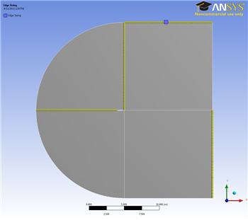
Once the edges are selected, in the Details View Window select Geometry > Apply. Next, select Type > Number of Divisions. Change the Number of Divisions to 50. Select Behavior > Hard. We also want the mesh to have a bias, so select the first bias type: Bais > ----- — - -, and give the edge sizing a Bias Factor of 150. The Edge sizing should now look like this:
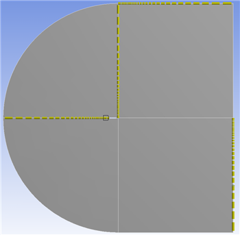
Notice that the element sizes get smaller toward the airfoil. This will give us a better resolution around the airfoil where the flow gets more complicated. Create a new edge sizing with the same parameters, but choose the 4 remaining straight edges (see figure below). The number of divisions will still be 50, but now we will be selecting a different biasing type by selecting the second Bias option: Bias > - - — -----. Again, set the Bias Factor to 150.

Edge Bias
It is important to make sure that the edge divisions to this point are biased toward the center of the mesh; otherwise, you may run into some problems later. If your mesh does not match the pictures in the tutorial, make sure to change the parameters of the mesh to make sure that they do. This might mean choosing different edges for the different biasing types than those outlined in this tutorial.
Finally, create a third edge sizing, and select the rounded edges as the geometry. Again, select Type > Number of Divisions, and change Number of Divisions to 100. Select Behavior > Hard. This time, we will not bias the edges.

Now, select Mesh > Generate to generate the mesh. It should look like this: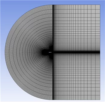
Named Selections
Now will assign names to some of the edges to make creating boundary conditions for the mesh easier. Let's recall the boundary conditions we planned in the Pre-Analysis Step:

The edges highlighted blue are the inlet, the edges highlighted red are the outlet, and the airfoil is highlighted white in the middle. Now we are ready to name the sections. In the Outline window, select geometry to make seeing the edges a little easier. Again, make sure the edge selection tool ![]() is selected. Now, select the two vertical edges on the far-right side of the mesh. Right click and select Create Named Selections. Name the edges
is selected. Now, select the two vertical edges on the far-right side of the mesh. Right click and select Create Named Selections. Name the edges outlet. Next, select the edges that correspond to the inlet of the flow as defined by the picture above. Again, right click and select Create Named Selections and this time name the selection inlet. Finally, select the two edges making up the airfoil, and name the selection airfoil.
You are being redirected to our marketplace website to provide you an optimal buying experience. Please refer to our FAQ page for more details. Click the button below to proceed further.