Mesh — Lesson 4
In this section the geometry will be meshed. The cell numbers on the edges of the desired mesh are shown here:

In this section the geometry will be meshed. The cell numbers on the edges of the desired mesh are shown here:
Launch Mesher
To begin the meshing process, go to the Workbench Project Page, then (Double Click) Mesh.
You may want to generate a preliminary mesh by right clicking on Mesh (upper window) and then “Generate Mesh.”
Mapped Face Meshing
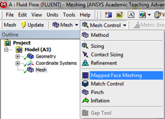
Here we are interested in creating a grid style of mesh that can be mapped to a rectangular domain. This meshing style is called Mapped Face Meshing. To incorporate this meshing style (Click) Mesh Control > Mapped Face Meshing as can be seen below.
Now, the Mapped Face Meshing still must be applied to the pipe geometry. To do so, first click on the pipe body which should then highlight green. Next, (Click) Apply in the Details of Mapped Face Meshing table, as shown below.

After clicking Apply, you should see “Geometry: 1Face.” Now, (Click) Mesh > Generate Mesh as can be seen below, and generate a rough mesh.

Edge Sizing
The desired mesh has specific number of divisions along the radial and the axial direction. To obtain the specified number of divisions Edge Sizing must be used. The divisions along the axial direction will be specified first. Now, an Edge Sizing needs to be inserted. First, (Click) Mesh Control > Sizing as shown below.

Now, the geometry and the number of divisions need to be specified. First (Click) Edge Selection Filter, ![]() , in the upper toolbar. Hold down the "Ctrl" button and then click the edges AF and BG. Both sides should highlight green. Next, hit Apply under the Details of Sizing table as shown below.
, in the upper toolbar. Hold down the "Ctrl" button and then click the edges AF and BG. Both sides should highlight green. Next, hit Apply under the Details of Sizing table as shown below.

Now, change Type to Number of Divisions as shown in the image below.

Then, set Number of Divisions to 100 as shown below.

Change Behavior to Hard for both Edge Sizing's.

Follow the same procedure as for the edge sizing on the other edges. Make sure to (Click) Mesh Control > Sizing every time. Then, generate the mesh by clicking Mesh > Generate Mesh. You should obtain the following mesh.

Detail around the expansion entrance FG is presented blow.

Mesh statistics can be found by clicking on Mesh in the tree and then by expanding Statistics under the Details of Mesh table. There are 22000 elements in the mesh above.
Create Named Selections
Here, the edges of the geometry will be given names so you can assign boundary conditions in Fluent in later steps. The left side of the pipe will be called "Inlet" and the right side will be called "Outlet." The bottom side will be called "CenterLine" and the other edges are called "Wall," as shown in the image below.

To create a named selections first Click Edge Selection Filter. Then click on the left side of the rectangle and it should highlight green. Next, right click the left side of the rectangle and choose Create Named Selection as shown below.

Select the left edge and right click and select Create Named Selection. Enter Inlet and click OK, as shown below.

Now, create named selections for the remaining edges and name them according to the diagram. Since the “Centerline” consists of two edges, when naming the centerline you should use "Ctrl" to select both parts. For the “Wall,” use “Ctrl” to select three edges.
Save, Exit & Update
First save the project in the Mesher window. Next, close the Mesher window. Then, go to the Workbench Project Page and click the Update Project button, ![]() .
.
If the Progress window shows error message like this: “Model information is incompatible with incoming mesh,” right click on Setup in the workbench and select “Reset”, then Update Project again.
You are being redirected to our marketplace website to provide you an optimal buying experience. Please refer to our FAQ page for more details. Click the button below to proceed further.