Tips for Transient Sample Mode Simulations in Ansys Lumerical INTERCONNECT — Lesson 4
Overview
This video lesson provides an overview of various tips for Transient Sample Mode simulations in Ansys Lumerical INTERCONNECT.
Waveguides
Waveguides can be used to transfer light bidirectionally between different circuit elements. In this video lesson, you will learn how to capture the time delay of the propagating modes in the waveguide for accurate simulation results.
S-Parameter
S-parameter elements are very common and important in circuits. In this video lesson, you will learn about appropriate filter settings based on the S-parameter's role in the circuit.
Delay Compensation
Simulation of resonators and feedback loops can be challenging due to the impact of additional time delays on the frequency-dependent response. In this video lesson, you will learn how to use the delay compensation property to resolve this problem.
Sample Rate
In this video lesson, you will learn some practical tips for choosing an appropriate sample rate for Transient Sample Mode simulations in INTERCONNECT.
Demo
This video lesson revisits the ring modulator simulation file from the frequency-domain simulation course and runs a time-domain simulation using the Transient Sample Mode. The simulation files used in the video can be downloaded below:
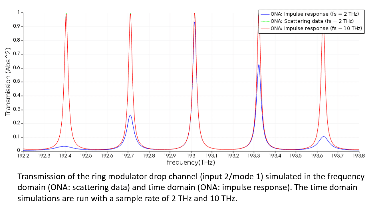
In the demonstration, the sample rate is set to 2 THz. This sample rate is sufficiently high to capture the correct time delays, and the free spectral range matches what we would expect from the analytical calculation. However, the peak values of the power transmission for the drop channel (input 2/ mode 1) are not uniform or close to unity, as we would expect. The figure below shows a comparison of the ONA results with “analysis type” set to “impulse response” (as in the demo above), and “analysis type” set to “scattering data”.

As we saw in the "Sample Rate" video lesson, this comparison can be made to check whether the sample rate of the transient sample mode simulation is sufficiently high. The disagreement in the peak values above shows that the sample rate should be increased for a better agreement.
The Root Element “sample rate” is increased to fs = 10 THz and the ONA “number of points” is increased to 10,000. The resulting power transmission is plotted below (red), along with the results previously shown for a sample rate fs = 2 THz. We now see good agreement between the time domain result with fs = 10 THz and the frequency domain result (green).
You are being redirected to our marketplace website to provide you an optimal buying experience. Please refer to our FAQ page for more details. Click the button below to proceed further.