Homework, Quizzes, Simulation Examples - Thermal Conductivity
Simulation Examples
Several simulation examples are provided here. Each of them comes with a description file, video instruction, and Ansys simulation file. All of the simulations are conducted by Ansys. Download student version of Ansys from here.
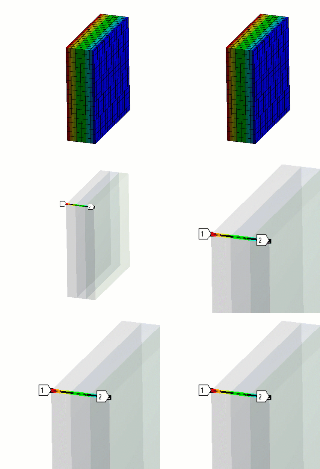
(1) Heat Conduction Through a Composite Wall
Composite walls are used to prevent heat from flowing in or out of structures. The thermal conductivity of the materials involved in building a composite wall plays an important role. The aim of this simulation is to show the temperature variation throughout the wall thickness. Try to use different material properties for different layers and plot the temperature variation through the wall thickness. Download the zip file and extract the contents. Go through the Readme file. Follow along with the provided How To Video file.


(2) Thermal Insulation of a House During Winter
During winter, we face a lot of snow and a drastic drop in outside temperature. The insulation of a house provides resistance to heat flow and can significantly lower heating costs. By installing insulation materials between the walls of the house, we can reduce the conductive heat flow. Download the zip file and extract the contents. Go through the Readme file. Follow along with the provided How To Video file.


(3) Laptop Heating Problem
Laptop heating is a very common problem we face while working on high-end computational activities. Overheating of a laptop can damage the electric components inside it. The main sources of heating inside the laptop are the CPU and the battery. And when they get heated, they transfer heat to other connected components. Download the zip file and extract the contents. Go through the Readme file. Follow along with the provided How To Video file.


Homework
(1) Cylinder Head and Gasket Example
In an automobile engine assembly, the cylinder and head are very important components. Another crucial part is the sealing gasket placed between the cylinder and cylinder head. While the engine is running, the cylinder experiences very hot temperatures due to combustion within. In this example, we will study the temperature distribution within the cylinder, cylinder head, and gasket. In this case, the cylinder is subjected to hot gases from within while the outer surfaces are at ambient temperature. What do you think the temperature distribution will look like? Let’s try to find out through this example. Download the zip file and extract the contents. Go through the Readme file. Follow along with the provided How To Video file.


(2) Centrifugal pump model with thermal contacts
Centrifugal pumps are used to transport fluids in many different industries, e.g., sewage, agriculture, and petroleum. When the temperature of the fluid passing through the pump is high, we need to consider the thermal effect on the pump system. Usually, the parts of a centrifugal pump are made of metals. In this simulation, there are three different metal materials for different parts. Thermal contacts between the parts are defined with given thermal conductance values. Set up the model and try to identify the temperature differences between the parts. Now, if we change all the contacts to have perfect contact conductance, will the temperature of the pump increase or decrease? Try to use your engineering judgment to answer the question first and then use simulation to verify it. Download the zip file and extract the contents. Go through the Readme file. Follow along with the provided How To Video file.


(3) Clamped Pipe Example
A pipe system consists of the pipe itself and many joint parts. In industry, pipes are often used to transmit high-temperature fluids. Heat transfer analysis can be used to determine the temperature distribution throughout these parts to avoid design defects. In the simulation, thermal contacts are needed between the pipe and joint parts to ensure realistic heat transfer. Assign the default structural steel material and manually change the thermal contact conductance of 3,600 W/m2.0C. Define convection inside the pipe (film coefficient = 100 W/m2.0C, bulk temperature = 2000C) and outside the pipe (film coefficient = 10 W/m2.0C, bulk temperature = 22 0C), to model the heated fluid and air, respectively. Plot the temperature difference and temperature drop across the contact between the clamp and the pipe. Download the zip file and extract the contents. Go through the Readme file. Follow along with the provided How To Video file.


