Physics Setup — Lesson 4
Launch Fluent
To launch Fluent, double click Setup under Project Schematic.
Check the option "Double Precision." This will make the simulation more accurate, since Fluent will use twice as many bits in the calculations.

You can leave the rest as Default. Select Parallel if desired. Now press OK to launch Fluent.
Check Mesh
It is always a good practice to check the mesh, especially if you are importing a mesh that was not created by you. It is not rare to get matching errors; particularly with meshes that have multiple Cell-Zones like our mesh.
In order to check the mesh, you can click on Mesh > Check, which is located under the upper tab next to File.
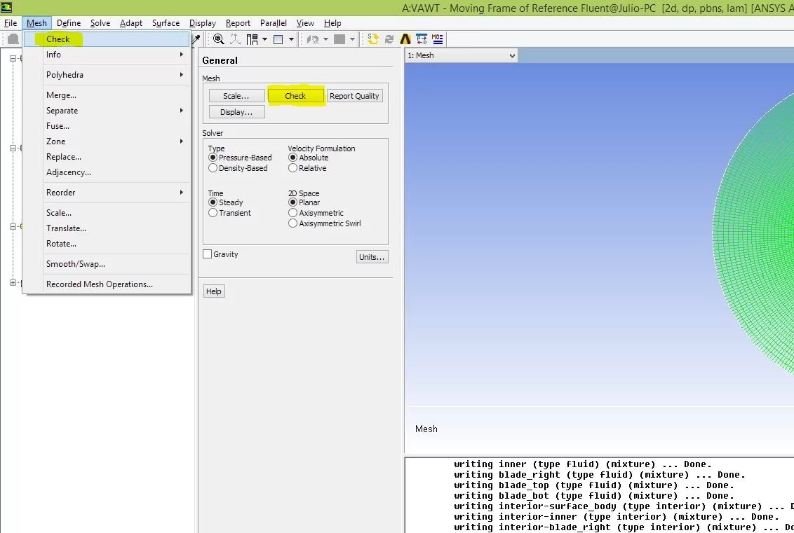
You can also note that when Fluent is first launched, an option to check the mesh is available under "General." You can see this highlighted in the above figure.
Lastly, you can type "mesh/check" and hit Enter in the messages box.
Create mesh interfaces
As briefly discussed before, we need to start by creating the interfaces between the different zones of the mesh.
To account for the rotation of the mesh, we cannot simply create one single mesh. Instead, we have to create sub regions or Zones of meshing.

The mesh created is "non-conformal," i.e., the nodes do not match across the interface, so we need to tell Fluent that the adjacent cells across that interface share information.
To make the "Interfaces" option appear, first go to "Boundary Conditions." Select the first Zone on the list, "blade_bot_in," and change the type to "Interface." Click OK in the pop-up window to keep the default name.

Note that the "Mesh Interfaces" option appears on the main menu to the left.
Go ahead and set the other interfaces Boundary Conditions. There is no quick way to do that as Fluent does not allow you to Copy Interfaces Boundary Conditions. So, proceed as before and assign the following Zones to the Interface:
blade_bot_in
blade_bot_outer
blade_right_in
blade_right_outer
blade_top_in
blade_top_outer
hub_inner
hub_outer
Now we're ready to finally create the interfaces!
In our case, each pair of Interface Boundary Conditions will be an Interface Zone. So, there will be four zones in total.
Highlight "Mesh Interfaces" and click "Create/Edit..."
In the first box, "Mesh Interface," write "blade_bot". That's the name of the interface. Under Interface Zone 1, select blade_bot_in. For Interface Zone 2, select blade_bot_outer. Click "Create." The window will not close by itself so go ahead and close it.

Repeat this and create the remaining three interface zones.

Be careful to select the correct in-outer pairs!
Note: You do not have to close the Mesh Interface window all the time. After clicking "Create" you can go ahead and give the name for the new Interface and create it.
By the end of this step, your window should look like this.

Set Solver information
Now, resuming...
Select the first option under "Setup": "General."
Here we can change key information about the solver, whether it's steady or transient, planar or axisymmetric, etc.
For our problem, you can leave the default options, i.e., Pressure-Based, Steady and Planar.
Lastly, click "Units" and change the "angular-velocity" unit to rpm.

Set the Model
Here is where we tell Fluent all the simplifications for the model it can assume. For instance, here you specify if the model is Inviscid, Laminar or Turbulent, if you should consider the Energy Equation (for supersonic flows), and other options.
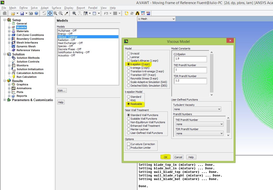
For us, we will be considering turbulence, and we will use the k-epsilon Realizable model.
Highlight "Models" and double click the third item in the list, "Viscous – Laminar." Select "k-epsilon (2 eqn)." Change "k-epsilon Model" to Realizable. Retain the rest as default. Click Ok.
Materials
We will use the default properties for air. Go ahead and check if they are correct.
Highlight "Materials" and double click "air" under "Fluid."
Density: 1.225 kg/m3
Viscosity: 1.7894e-05 kg/m-s

Cell Zone Conditions
Here we specify to Fluent the material of each meshed zone (usually correct by default, unless we create a new material).
Also, we set this if we are solving a moving mesh problem or moving frame of reference problem (our case). We can also set the centroid of each zone and the angular velocity of that zone here.
Highlight "Cell Zone Conditions." Note that our problem comprises five zones:
- blade_bot: corresponds to the mesh around the bottom blade
- blade_right: similar to above, but for the right blade
- blade_top: similar to above, but for the top blade
- fluid-surface_body: corresponds to the big circular mesh around the main geometry of the turbine
- inner: corresponds to the zone between the blades inside the hub
These are the same zones described previously when creating the mesh interfaces. We will have to edit parameters for each of them.
fluid-surface_body
Highlight fluid-surface_body and click "Edit...".
No options should be selected here, and the material must be set to air. This is the default. You can verify that and click Ok.
inner
Highlight inner and click "Edit." Here we will set that the inner portion of the hub is spinning, adding more terms to the equations to account for local acceleration, even though the mesh is not actually moving.
Right under "Material Name," select the first option "Frame Motion." We want to specify the angular velocity and the origin about which the mesh turning.
From the geometry, the centroid is at the global origin (0,0). Verify that that is the input.
From the problem statement, the turbine is spinning at 40 rpm, so go ahead and input 40 to "Rotational Velocity." This is the absolute velocity. Note that "absolute" is selected under "Relative Specification."
The rest you can keep as default. Click Ok.

blades
Highlight blade_top and click "Edit...".
Again, select the "Frame Motion" option. Now, in order to make the blades rotate and keep the same relative position to the hub, select the "inner" Cell Zone under "Relative Specification." The relative velocity will be zero.
We need to do some basic geometry to find the rotating center. The blades are located 0.04 m from the center of the turbine. The top blade is 120 degrees from the (positive) x-axis. So:
x=0.04*cos(120)=-0.02 m
y=0.04*sin(120)=0.034641 m
Go ahead and input that for X and Y of "Rotation-Axis Origin (Relative)."

Do the same for the right and bottom blades. Select "Frame Motion" and make it relative to the "inner" cell zone. The needed values for centroid and angular velocity are summarized below.

Don't forget to select the relative motion!
It's good to go back and check each cell zone to avoid messy errors in the future!
We are now ready to set the other boundary conditions.
Boundary Conditions
Remember that we had already set some Boundary Conditions, before doing the Mesh Interfaces. However, we still need to tell Fluent where walls are located and specify some pressures and velocities.
Velocity at the inlet
First, specify the velocity at the inlet.
Locate and highlight "farfield1." Change its Type to "velocity-inlet."

Click "Edit." In "Velocity Specification Method," change to "Components." Set "X-Velocity (m/s)" to 10.
Under "Turbulence," change the "Specification Method" to "Intensity and Length Scale." Set the "Turbulence Intensity (%)" to 5 and the "Turbulent Length Scale (m)" to 1.

It's very important to change the Specification Method for the Turbulence to "Intensity and Length Scale," otherwise your model won't converge.
Pressure at the outlet
Locate and highlight "farfield2." Change its Type to "pressure-outlet."
A window will pop up. Leave "Gauge Pressure (pascal)" as default (zero). Apply the same turbulence conditions as describe above for Velocity at the inlet boundary condition.

Note: If this window does not automatically pop up, click "Edit..." next to where you specified the Type of the boundary condition.
Wall
We need to tell Fluent that the blades of the turbine are walls (i.e., no-slip condition, or no velocity normal or tangential to there), that are rotating together with the mesh around it.
To do that, select the "wall_blade_bot" zone. It should be already assigned to the Type "wall" (if not, do so). Click "Edit."
Under "Wall Motion" change to "Moving Wall." On the new options that appeared, change the Motion to "Rotational." Now, specify the Rotation-Axis Origin with the same corresponding values as before. X=-0.02 m, Y=-0.034641 m. Click Ok.

Now, let's copy that to the other blades. Click "Copy," near to "Edit." On the left list, select the boundary condition you just made,"wall_blade_bot." The two other wall_blade boundary conditions appear on the right column. Go ahead, click on both (the two must be highlighted), then click "Copy."

Click Ok on the window that popped up.
Lastly, we need to change the Origin of rotation of the copied wall boundary conditions. To do so, select each of them ("wall_blade_top" and "wall_blade_right"), click "Edit" and change the "Rotational-Axis Origin" to the respective centroid.

Observe that the options selected for the first wall boundary condition were copied to each new one.
Now that we're done with Boundary Conditions, we're almost ready to run the simulation!
Save your project.
You are being redirected to our marketplace website to provide you an optimal buying experience. Please refer to our FAQ page for more details. Click the button below to proceed further.